- Welcome to the Kancolle Wiki!
- If you have any questions regarding site content, account registration, etc., please visit the KanColle Wiki Discord
User:Remi Scarlet/Blog/FurutakaKaiNiCosplay
Well, here goes nothing.
What The Fuck Is This

I'll be making these blog posts as I work on my Furutaka Kai Ni cosplay props and whatnot. The posts will be made with my progress, process, description/explanation and some random musings.
Feel free to message me on Facebook if you want to ask me questions about it or shoot me a message on our IRC, #kancollewiki@irc.esper.net. If it weren't obvious enough by my wiki username, my nick on IRC is also Remi_Scarlet. Alternatively, feel free to use the discussion page on this page to talk.
That said...
Goals and Whatnot
So obviously with any cosplay, there are a lot of levels of "completion" and whatnot. For this cosplay, I plan on making this one of my most ambitious and difficult cosplays to date. Some things I plan on incorporating include but are not limited to:
- Rotating and controllable cannons via button input on my hands
Retracting barrels to emulate the cannons "firing"- Firing sounds via a miniature speaker system (Maaaaaaybe)
POSSIBLY fake "smoke" from the barrels upon "firing"
I estimate the total cost for this cosplay to hit possibly in the ~$500 range depending on how fancy I decide to make this. Again, this is by far my largest and most ambitious project yet.
Edit: As of 6/1/15, I have now surpassed over $500 in materials. My wallet is crying horrendously. I don't even know where all the money went. It just evaporated.
Hah. $1,200. Bye.
Materials
Foamboard
- This is the type you can buy at any craft store such as this. Make sure to buy these in-store because these are hella expensive if you buy online. If you buy a non-brand one like Elmer's from your local craft store, you can get these for even cheaper. I get mine for like $4 or $5 per board. I just got a bunch when they were on sale so I paid $3.50 each kek
Cardstock and Poster Paper
- This is essentially just "thicker" paper. Look at my day 1 post and I have a pretty good explanation on what type I buy and how to use these. I utilize the poster paper for larger portions that require reinforced paper like the smoke stack backpack.
Wood of Various Sizes
- I'll buy dowels, square dowels (whatever they're called), boards and various other cuts. Basically whatever I deem necessary.
Paints
- Generally I just buy a shitton of spray paint and some masking/painting/marking/whatever tape to get certain types of paint patterns. More on this whenever I start painting my props.
Glue
- Elmer's glue and wood glue along will be my primary weapons of choice with the occasional assistance from the clear Gorilla glue and some hot glue when the occasion calls for it. I rarely use, but have needed, super glue in the past for small stuff.
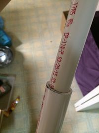
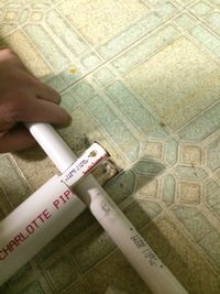
PVC
- Lots and Lots and Lots and Lots of PVC. For Furutaka my primary cuts are 0.5inch, 0.75inch, 1inch, 1.25inch and 1.5inch cuts.
Screws, Nuts and Bolts
- I generally stick to various lengths of 1/4th inch screws with plenty of nuts and bolts to accompany. If you go to Home Depot, you can get like a box of 1/4th inch washers for $5 and 1/4th inch nuts for like $10 so I just suggest getting those. They're generally 100-packs.
Craft Foam and Styrene Sheets For making some portions like the food/shin armor and the tubings around my leg that hold the crane and torpedo tubing, I utilized craft foam and styrene to mold them. This Website has a wonderful tutorial on craft foam and styrene armor-making.
Tools
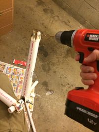
Power drill
- I just bought this for the first time in my cosplay career and HOLY FUCK WHY DID I NOT INVEST $40 INTO A CHEAP ONE. THESE ARE A FUCKING LIFE CHANGER DON'T SKIMP OUT IF YOU CAN AFFORD IT. POWER DRILLS MAKE LIFE 100x EASIER WHEN DRILLING HOLES. Like, I used to hand drill holes by screwing small drillbits and progressively working my way up with thickening diameters and it's take like 5 minutes just to get one hole done... with this magical tool, I can suddenly get a hole in 15 seconds. It's fucking amazing.
Saw
- Get a handsaw, the type that looks like a stubby U with a saw band attached across the two legs.
Wrench and Pliers
- If you don't have these, good fucking luck tightening the screws and nuts lol
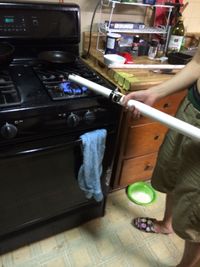
Some Source of Heat
- I just use my stove. This is for heat bending PVC.
Vice
- These are so fucking helpful for keeping something in-place while you work on it. You'll notice that I'm using this all the fucking time.
IMGUR LINK FOR THE IMAGES
Since looking at images on wiki is terrible, I'll ALSO be uploading all images used here onto the following imgur link so it's more browsing-friendly. All images are uploading in order of newest to oldest.
Day 1
Date: 5/21/15
Time spent: ~3 hours
Show/Hide Day 1
So as with all good things, there are some boring parts that come with it as well. That's usually the beginning with making cosplay props :(

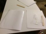
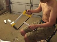
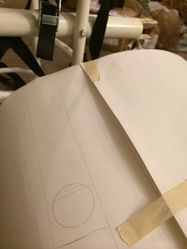
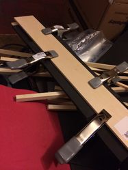
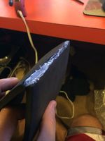
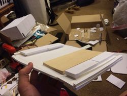
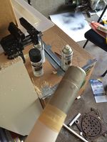
Paper Layering
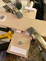
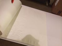
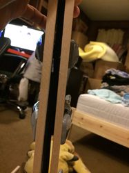
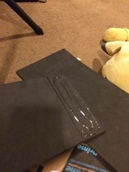
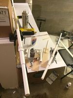
On the first day, there were two primary things I got accomplished. Well, to be specific I started on both of them. With my style of prop making, I utilize rigid foam boards (The kind you can buy from any art store, not the lionboard/EVA boards/more rare varieties) and paper.
"Whoa, whoa, whoa. Paper?", you might ask me. People who don't do cosplay props might not realize, but paper is actually not that uncommon a material to be used as one of the primary materials. Here's the trick. You have to get some of the thicker lines of paper, the kind you usually use for business cards or fancy letters and papers. These might go by the name of "cardstock" paper or just by paper weight classifications.

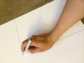
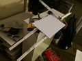
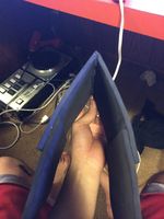
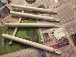
What I do with these papers is that depending on the required strength of the object I'm making out of this paper is, I'll layer it two to three times via spreading a thin layer of glue on one sheet, layering another clean sheet on and letting it sit under pressure for at least 24 hours. It's crucial that the layer of glue you apply is as thin as possible while making sure you don't leave any air holes, eg spots that don't have glue. If your glue is too thick, then it'll never dry and when it does, it'll be like a solid layer of glue. On the other hand, if your glue is too thin and you have pockets of no glue, then when you start cutting and using the layered sheets, you'll get areas where the sheet is... well, not combined into one layer. Also be sure to get the edges of the papers. These are important too!
Examples can be seen on the second and third images on the left as well as the second image on the right. Personally, I find using popsicle sticks that you can buy a bag for $0.99 at an arts and crafts store to be a great way to spread the glue very evenly. As for the glue, as shown in the picture, I just get a tub of Elmer's glue and it works like a freaking charm. Great stuff.
Now how many of you immature bastards thought "Ew, sticky white stuff, teehee!"? Don't worry, I thought that too. Anyway, make sure to get as thin as possible a layer on the sheet while making sure you don't make it invisibly thin.
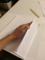
And once your glue is layered, make sure to get a clean sheet of paper and layer it on.
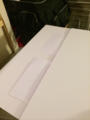
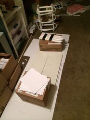
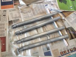
And here we lay the layered pieces of paper to rest under more foam board and an unpictured box of a lot of heavy textbooks. I guess that's one use for those $200 university textbooks I never used!


Planning and References
So now that's all good and done, what about actually planning the actual making of the props? Staring at paper dry is hardly anyone's definition of fun cosplay making. Well for starters, since I'm recreating a cosplay of a character, the logical thing to do is simply look up reference images. The key here is that you want to get a really good feel for the character's look from all possible angles. Unfortunately, this isn't always possible with just official sources. Kancolle is a great example of this due to the limited "official" art available for most characters. This is where you have to use some imagination in combination with fan art to fill in the gaps of what the official sources might be lacking in terms of angles.
Basically, before you start anything you should have a pretty good idea of the general location, size, look, feel and workings of all the major components of a character's propset. For me since I'm doing Furutaka kai ni, I needed to be able to visualize what her arm cannon, shoulder cannon, exhaust backpack thing, torpedo racks, boots, etc all looked like, how they aligned with each other and how it all worked cohesively as a unit.

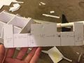
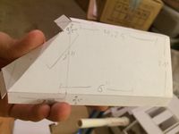
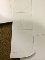
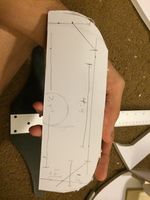
Once I got an idea of that, I started sketching out some diagrams based on official art to get a reference for size and dimensions of all the major components I'd need. I haven't finished doing this step yet, but I've made some progress on the arm cannons for now. For the cannon, I did a combination of tracing as well as just visualizing test dimensions and seeing what seemed to "work" best. Eg, when I look at the official art I know that the front cannon should have a certain feel with its shape and size. That said, I guesstimate what kind of proportions/dimensions would look appropriate on me (my arm) and visualize these dimensions and shapes on my arm. I keep adjusting until I find a visualization I think works well and write them down. Another important point is that with anything you trace, assuming you trace well, the proportions of the trace will technically be the most "accurate" and "official", so just make them proportional to your own body as it is to the character. Eg, I measured my should to the first knuckle on my fist to be about 26 inches. Since I had a trace of the entire arm cannon which started at the first knuckle and ended at the shoulder, I just set that as my standard. The trace was almost exactly four inches long so I scaled it so that one inch on my scale trace was approximately 6 inches in real measurements. From here, everything else worked out via proportions to get a rough dimension estimate for the rest of the arm cannon.

And for Day 1, that was about the extent of how far I got. I expect to continue working on diagrams and dimensions for Day 2 and getting a rough estimate on the amount of materials I need as well as maybe even starting on actual material work.
Day 2
Date: 5/23/15
Time spent: ~0.5 hours
Show/Hide Day 2
So I actually didn't get to work on this a whole lot today cuz I was busy playing other games and frantically finishing up my completely neglected weeklies, but yeah. Running 2-2 and 2-3 like 10 times and not getting sent to a single node with a transport ship is really frustrating. Especially when you're literally one kill away from finishing the quest.
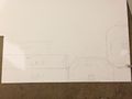
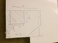
Anyway, so in the ~30 minutes I actually worked on the cosplay, I decided to try and plan out the sketches a bit more. This time, I worked on the torpedo mount on Furutaka's left leg.

To summarize, what I'm thinking of doing here is getting one inch PVC pipes for the torpedoes themselves. I'll likely get a set of 1.5" PVC and heat bend them to be smaller in diameter so they snugly fit the 1" diameter ones and use that as the torpedo housing. On top of this, since the torpedo mount connector (the thing that connects the mount to Furutaka's leg) will need to be rigid and resistant to stress and strain, I'll likely make the actual housing component out of a stronger and more durable material. Perhaps I'll do a combination of a carve-able expanding foam and cutting out a torpedo housing for it and have a wooden flat base to connect it onto the actual mount connector. That probably made no sense. Gah, I usually just #yolo these things and don't bother explaining to anybody so trying to explain the method to my madness in words is hard. Also I'm terrible at drawing so the diagram probably doesn't help much.
Basically, torpedo mount will have two primary components and a couple of sub-components on one of the primary components. First component is the "rigid torpedo casing" which will be made from the sub-components of expanding foam and wood, likely held together with glue and a few screws/washers/nuts. The second component will be made from more fragile materials like the foamboard and layered paper. In the final product, the foam sub-component shouldn't be visible from the outside. The torpedo itself will likely be crafted from 1-inch PVC pipes and the housing that cups around the torpedo will be made from heat-bent 1.5-inch PVC piping.
This should make a lot more sense when I actually start making the stuff and have pics to show what I mean. Words are hard... especially at 10am when I haven't slept yet. I should go sleep now.
Day 3
Date: 5/24/15
Time spent: ~2 hours
Show/Hide Day 3
Purchasing and Fire
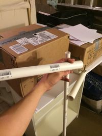
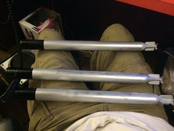
So today I went out and bought some PVC piping that would act as various parts of the propset as per yesterday's sketches. All in all, I figured that I would need about 50 inches of 1.25inch diameter piping, 50 inches of 1inch diameter piping, 60 inches of 0.5inch diameter piping and some ~20 inches of 0.75inch diameter piping as internal couplings for the pipes. I also bought some PVC caps which will act as the torpedo heads. While at Home Depot, I also decided to go ahead and stop skimping out and buy a real saw. Let me tell you, using an actual saw meant for cutting pipes beats the hell out of using those cheap arts and crafts knives.

So the idea for today's pipe purchases were so I had the materials needed for all the long pipe-y parts of the cosplay on hand. This includes turret barrels, turret barrels, more turret barrels and some torpedoes. Keep in mind, Furutaka kai ni has three cannons and a torpedo mount. That's six barrels and four torpedoes, equalling 10 long stick things. According to my sketches and calculations (which slightly changed from Day 2's), the barrels would be between 8.5 and 9.5 inches long and the torpedoes would be about 15 inches long.
A cool note about the 1.25inch inch piping is that they're just large enough to comfortably, but not too snugly fit the 1inch pipings. What I'll be using them for is the torpedo mount's torpedo housing. If you look at the images of torpedo mounts, you'll notice that there are thin half-pipe encasings on the upper half of the torpedoes. Due to the naturally well-fitted and shaped nature of the 1inch and 1.25inch pipes, I will be doing just that with the two pipes. Due to this, I have also changed my plans about the expanding foam encasing for the torpedoes. Instead, I will likely simply have a wooden base that's sturdy to connect the torpedo mount to my leg and use standard foam board beyond that with holes cut out to snugly fit in the 1.25 inch pipings.
Anyway, so in terms of actual progress with making stuff, I confirmed that I could use heat bending to soften the PVC piping to fit with each other. As it stands, without heat bending you can't fit a 0.75inch PVC into a 1inch PVC as they're just slightly off-sized. However, with application of heat to the PVC, you can soften it enough to "force" the smaller pipe into the larger one. Given enough pressure and once the pipes cool, they'll basically be lodged in there for good so no worries about it falling out.

Generally, it's better to use a heat gun instead of an open flame since... well, you can see that the PVC is kind of on fire. Wheeee.
When shoved in, the smaller piping will fit very snugly into the larger pipe.


If you're wondering why the hell I needed to do this weird pipe fitting thing, it's because I also had a 0.75inch pipe cap which coincidentally has the same outer diameter as the 1inch diameter pipes. That said, I decided to combine the 1inch pipe and 0.75inch pipe cap together to make it look like a single pipe with a cap. Obviously, aesthetic embellishments will be applied to smoothen out the little line where the pipe cap and pipe actually meet and whatnot, but that comes later.
So now that I had confirmed these things fit together, all I had to do was get the torpedo propellers and they'd basically be done!
...Except life isn't that easy, is it?
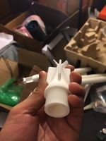
Torpedo Propellers
So after thinking about how the hell I could make a small-scale yet intricate propeller system for the torpedo, I figured that it's probably impossible to hand craft something that would look nice, be sturdy and be able to fit onto a PVC's piping diameter. Thus, I decided to opt to one of my favorite additions to cosplay, the 3d printer. After deciding that I would likely need to design an print out my torpedo propellers to make them look top notch, I set to work for an hour or so to come up with the following. The first three images are the propeller portion with the torpedo's main body attached for reference. The fourth image is what I would actually be printing.
Long view shot
Close up and from the side

Diagonal shot
The actual part I'm going to be printing


So with this, I figured my issue with the torpedo is solved. For now, I still need to go and print the parts so we'll see if this works as well as I'm hoping.
I'll likely start thinking and working with the cannons next time!
Day 4
Date: 5/25/15
Time spent: ~1.5 hours
Show/Hide Day 4
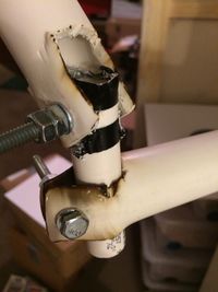
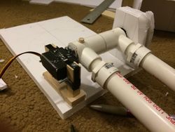
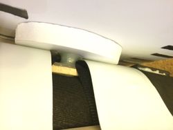
So outside of actually just making a working super arm cannon that characterizes Furutaka kai ni a lot, one of the difficulties of making this cosplay is the black cannon that Furutaka has.

The problem with this part are the mechanical limbs and joints that connect them. So to actually make this with a mechanical shop isn't too bad since you can machine your individual parts and whatnot. Unfortunately, I'm not a mechanical engineer and even though I do know my basic CAD and whatnot, I have no access to equipment for just machining out my parts (Which would have made life a lot easier, albeit more expensive).
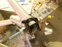
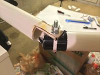
So the majority of today's "work" was actually spent just lying on my bed and staring at the ceiling while thinking "How the fuck.". After about 10 minutes though, I suddenly got an idea. Since I already had plenty of PVC pipes lying around and it was easy enough to go buy more, I decided I would try to tinker around with the PVC piping to see if I could emulate hinge and pin joints with them. After hacking away at PVC with my saw and lighting the pieces on fire over my stove, I finally ended up with something like this for a hinge joint.

So this is actually pretty beautiful in my opinion, the fast prototyping and resultant aesthetic lacking aside. So the amazing this about this is that it basically serves every function I need it to do and that I can actually make it a "stiff" joint, as in I can move it around if I tried but once I let go, the joint will stay "in-place". The "stiffness" can easily be achieved by adding something to increase friction such as adding a layer of duct tape at the connection point of the two pipes and tightening the bolt on the screw a lot. By double nutting the screw, this would ensure that the nuts and resultant pressure wouldn't come loose.
With this solution, I figured out that I can actually make the limbs and hinges work very nicely for a ridiculously cheap cost. Compared to CADing and machining out the parts, just grabbing some PVC pipes, screws and nuts might as well be free by price comparison. The only part I haven't covered here is the pin joint. While the construction of a pin joint itself would be very easy by simply making the same U cuts in the thicker piece of PVC and laying the thinner piece in the U shaped crevice, I would still need to figure out some method of "stiffening" this form of joint. That said, I believe with some clever application of friction-inducing materials and more tightened screws should solve the issue here as well. I'll obviously make updates on this subject once I have a chance to head to Home Depot at the end of the week and go buy more materials.
So with that, here are a couple of photos demonstrating stuff.
"Example" of how the hinges would work out. Front of the fat tube would be where the black cannon goes.
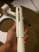
Flattening the flap of PVC via heating with fire and rolling flat with another, thinner, PVC pipe.
Mostly flattened example.

Closeup while not connected via screw.


Day 5
Date: 5/26/15
Time spent: ~2.5 hours
Show/Hide Day 5
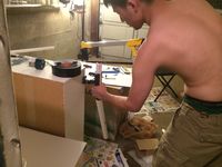
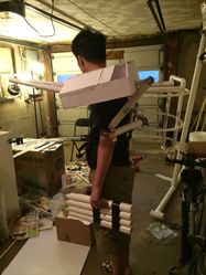
So I went out to Home Depot today and went ahead and splurged $120 on equipment and materials. Also blew $60 at an art store for other materials. Anyway, carrying back near $200 of equipment and materials was not something I would have thought was possible. I feel like I might have dropped a few things along the way.
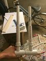
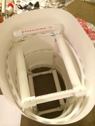
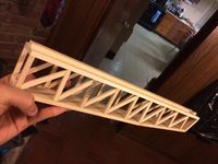
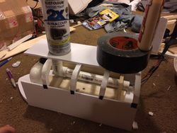
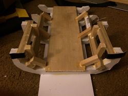
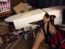
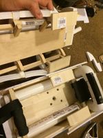
That said, today I went ahead and continued my work from yesterday by constructing the frame of Furutaka's shoulder cannons. Again, like I said with yesterday's post, this initially posed a large problem for me because I wasn't sure how I could make a joint frame that would be stiff at the joints, be durable, strong and able to hold the weight of the cannon itself. Thankfully, because of what I thought of last night, I figured it'd be worth a shot at trying to execute it. I basically just spent the entirety of today drilling, roasting, rolling and screwing PVC pipes together to get the images below. I won't add much text since what I did is pretty much the same as yesterday, just in more detail and depth. That said, enjoy the pictures. All of my criteria were met with the final frame I constructed so this is an amazing start.

Shot of me working on the PVC.
Shot of me working on the PVC.
Shot of me working on the PVC.
Please don't ever do this. This was incredibly dangerous and stupid but I lacked the proper tools to hold the pipe at this angle reliably
Roasting PVC
Drilling PVC

Drilling PVC Pt 2

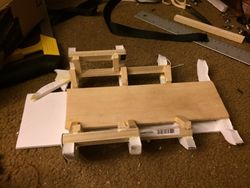
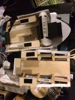
Frame of the side cannons complete (Note, cannon's on the wrong side atm. I just need to flip it lol)
Frame of the side cannons complete (Note, cannon's on the wrong side atm. I just need to flip it lol)

Frame of the side cannons complete (Note, cannon's on the wrong side atm. I just need to flip it lol)

Frame of the side cannons complete (Note, cannon's on the wrong side atm. I just need to flip it lol)
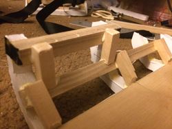
Closeup of joints
Closeup of joints
Closeup of joints


Day 6
Date: 5/28/15(A tiny bit on 5/27/15 as well)
Time spent: ~4 hours
Show/Hide Day 6
5/27
So I'll quickly go over what I did on 5/27/15 since I didn't get a whole lot done. Basically, yesterday was spent clicking around ebay and amazon buying various parts. So things I bought include
- Knee socks
- Thigh highs
- Cotton bodysuit
- Penny loafer shoes
- Pleated blue skirt
- Two 4.1kg-cm rated servo motors
For the servo motors, they have to be able to rotate two barrels that are have two components to them of certain length. The two components have different diameters.

Where [math]\displaystyle{ a }[/math] is pipe of diameter 0.5inches and [math]\displaystyle{ b }[/math] is pipe of diameter 0.75inches.
Note that with servo motor ratings, [math]\displaystyle{ kg }[/math]⋅[math]\displaystyle{ cm }[/math], it seems that it's just it's torque without the gravity component calculated in. The [math]\displaystyle{ \tau }[/math] I use in the calculations isn't actually torque but it's the same idea so I use the symbol for it, even if it's technically incorrect.
[math]\displaystyle{ CoM }[/math] is Center of Mass
| Pipe [math]\displaystyle{ a }[/math] | Pipe [math]\displaystyle{ b }[/math] |
|---|---|
| [math]\displaystyle{ \lambda_a = \frac{100g}{24inches} = 4.16\frac{g}{in} }[/math] | [math]\displaystyle{ \lambda_b = \frac{150g}{24inches} = 6.24\frac{g}{in} }[/math] |
| Given [math]\displaystyle{ \ell_a = 7in }[/math] | Given [math]\displaystyle{ \ell_b = 4in }[/math] |
| [math]\displaystyle{ m_a = \lambda_{a}*\ell_{a} = 24.96g }[/math] | [math]\displaystyle{ m_b = \lambda_{b}*\ell_{b} = 29.12g }[/math] |
| [math]\displaystyle{ d_{{CoM}_a} = \frac{4in}{2} = 2in }[/math] | [math]\displaystyle{ d_{{CoM}_b} = 4in + \frac{7in}{2} = 7.5in }[/math] |
| [math]\displaystyle{ \tau_a = m_{a}*d_{{CoM}_a} = 49.92g }[/math]⋅[math]\displaystyle{ in }[/math] [math]\displaystyle{ \tau_a = 49.92g }[/math]⋅[math]\displaystyle{ in*\frac{1kg}{1000g}*\frac{2.54cm}{1in} }[/math] [math]\displaystyle{ \tau_a = 0.127kg }[/math]⋅[math]\displaystyle{ cm }[/math] |
[math]\displaystyle{ \tau_b = m_{b}*d_{{CoM}_b} = 219.56g }[/math]⋅[math]\displaystyle{ in }[/math] [math]\displaystyle{ \tau_b = 219.56 }[/math]⋅[math]\displaystyle{ in*\frac{1kg}{1000g}*\frac{2.54cm}{1in} }[/math] [math]\displaystyle{ \tau_b = 0.558kg }[/math]⋅[math]\displaystyle{ cm }[/math] |
[math]\displaystyle{ \tau_{total} = 0.127kg }[/math]⋅[math]\displaystyle{ cm + 0.558kg }[/math]⋅[math]\displaystyle{ cm = 0.785kg }[/math]⋅[math]\displaystyle{ cm }[/math]
And since I have two of these barrels, I needed a servo motor with at least a kg⋅cm rating of [math]\displaystyle{ 0.785 * 2 = 1.57kg }[/math]⋅[math]\displaystyle{ cm }[/math]. Since it's always better to err on the side of caution, I decided to just go overkill and get a 4.1kg⋅cm rated servo.
Shoutout to the Kancolle USA group because I completely forgot how torque worked. It's been a few years kek. And to think I was originally a mechanical engineering major a long time ago.
That said, let's move onto what I actually did today.
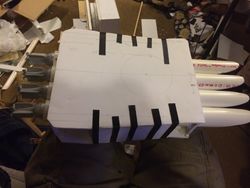
5/28
So today, I decided to actually start working on the cannons since I'd been delaying them for a few days now. That said, I didn't really plan too much out other than some basic goals for dimensions. I aimed for about a 12in x 4.5in x 7.5in frame for the body and so I decided to go ahead and run with that. Images will likely serve as better explanation so I'll do that gallery thing again with explanations for the images in the annotation. Again, feel free to look through my Imgur Album for easier viewing of images.
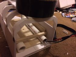
Double barrel cannons for shoulder mount on Furutaka kai ni
Applying pressure to wood glue to elevate contact-point with board due to screw head
Process of cutting foamboard with an x-acto knife
Preliminary cutout sketch with some measurements
Loosely attached cutouts (preliminary)
Attaching cannon base to PVC frame
Cutout of front cross-sectional support of cannon
Attaching smaller pieces together before attaching to main cannon body
Shot of the used wood glue
Front wall of cannon. Note the depressed cut to allow cannon barrels to move
Glued and combined shot of cannon without wall coverings
Another shot of cannons before wall covering
Closer shot of cannon barrels in the frame
Back view of cannon


Day 7
Date: 5/29/15
Time spent: ~4 hours
Show/Hide Day 7
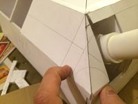
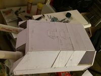
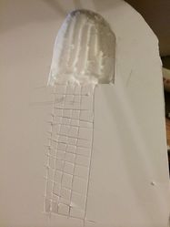
So after trying to avoid the problem for a few days, I finally gave in and decided to work on the roofing and walls for the shoulder cannon. Basically the reason I didn't want to start on this so much was because I felt like measuring out and cutting the front wall where the cannon barrels stick out would be annoying since... well, I'll just show a pic.

Something I should also note here that the top piece was inserted after cutting away about 0.25inches of the top from the horizontal support grid. You can see it in the following picture, but the tip of the slope actually covers the thickness of the top foam board. Those words probably made zero sense so just look at the image.

That done, I had to actually start cutting out test cuts from non-prepared paper to make sure my measurements and whatnot were correct. Remember from day 1 that I had prepared a few sheets of "layered" paper so as to act as a sturdier and more versatile "sheet". As a note, I've been making about 4 of these every other day or so, even though I haven't been denoting as such on the blog.

Measuring out the exact dimensions can be a bit difficult for stranger cuts and locations such as the diagonal corners of the cannon's front, as denoted earlier. As such, I basically did some measurements and trig to get the supposed lengths and sizes for the corners and hoped for the best. A clever trick I used here is that for the triangular flap that's at the end of the half trapezoid, I knew the triangular cut had to have a 1inch leg and a 2.75inch leg so I made a circle with 1inch radius and used a ruler to connect the third leg's endpoint to the point on the curve that made it exactly 2.75inches. As it turns out, which should have been obvious if I had thought about it a bit, that it's just the tangent line to the curve. This part also probably made zero fucking sense so just look at the image. That done, I now had to simply cut out the slice with my X-acto knife.

Cutting out the paper. And my gf's boba plush.

Test aligning the example cutout
Fitting


That all said and done, I decided my cut was mostly good and just needed a few small adjustments. One of these adjustments was that the triangular flap that went on the front side of the cannon needed to be adjusted a little bit. I accounted for these in my following "final" diagram that I proceeded to cut out and prepare.

Measuring out again on the layered paper

Likewise for the other side (left and right halves)
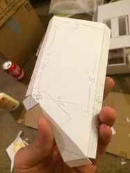
Diagram cut out. Since the paper is layered, you can very lightly cut along the lines with the X-acto knife to cut the "first layer" of the paper so it folds easier like this.
Another shot of the cutout


That done, I simply pasted it on and I ended up with a little something like this.

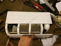
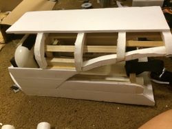
The rest of the progress done are pretty self-explanatory so I'll just do another gallery style dump here. The remaining images are basically showing the shell-like layering I'm doing for the rest of the body of the cannon and some final shots of the shell covering it except for the final piece which will be visibly missing.

Measurements for the layers along the top of the cannon.
Mostly finished. Just need to put on last layer at the very back.
Shot of the cannon's front.
From above.
Distanced and cannons aimed up
Close-up of the front


Day 8
Date: 5/30/15 and 5/31/15
Time spent: ~6 hours
Show/Hide Day 8
These "Day #" namings are kind of dumb because this is the second time I've had two days' worth of updates in "one day" lol. Oh well, too lazy to update sometimes.
Torpedo Tubing
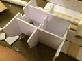
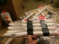
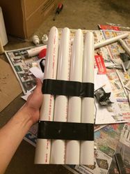
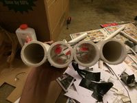
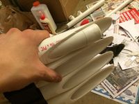
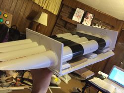
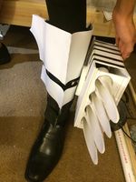
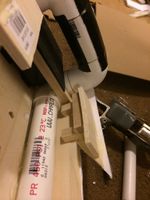
So Day 8 was filled with lots of PVC. Like, lots of PVC. So these two days I've basically been constructing the frames for the torpedo launcher and smoke stack backpack. Surprisingly enough, just doing these two things took a shitton of time because of how much PVC I had to cut, drill, screw and tape. I guess I'll just start in order for now. So first up is the torpedo casing. Since the torpedo encasing, or the tube that houses the actual torpedoes, are lined up in a row of four and immobile, I just went ahead and taped them together in a straight line.

With the tubes in place without a chance of movement, all I had to do was cut them and be done! Except nothing's ever that simple. The tubes actually ended up moving ever so slightly every time I started cutting a new part of the rack so I had a diagonally uneven cut across the PVCs. I ended up fixing by cutting a bit more diagonally and using filers to even out the pipes. After that, I curved the front tip to be rounded via more filing and then relashed the pipes together with more tape. Not I use gorilla tape, tape for the toughest jobs on earth!
Cutting the PVC rack diagonally.
After cutting, we end up with tubes looking like this

Filing down the tip to be a bit rounded
PVC lashed together with an example torpedo tip
Racks from a different angle
Back shot of racks
Side view of torpedo rack
Underside shot of torpedo rack


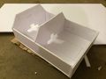
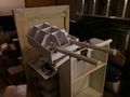
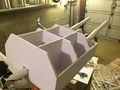
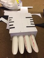
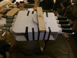
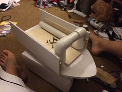
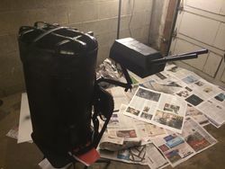
Exhaust Pipe Backpack
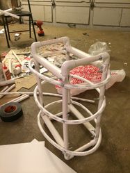
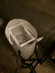
So the idea here was basically that just constructing a gigantic backpack that looks like the exhaust pipe thing that a lot of the ships have would be kind of annoying and difficult without making them ridiculously weak and prone to destruction. Since I want to be able to use this cosplay for at least a year, I decided to go absolutely overkill and construct and entire goddamn frame out of PVC for this portion.
So as you can see, this is literally a box frame made from PVC. Techniques I used to construct this are the same as what I used for the joints with the shoulder cannon. Except this time I made it so that it wouldn't really move around via simply positioning of the screws and the inherent nature of a cube.

Obviously though, since you can't really make a ovalular(I didn't know this was a word until I just googled it) frame with a box so I went ahead and lashed together some bendier PVC in an oval around the frame. This was done without any heat bending, I should note. There are multiple types of PVC and while I don't know the names of them at the top of my head, your local Home Depot or similar outlet should definitely have these. You should basically be able to bend the PVC like in the following pictures without too much difficulty. Two of the three rings were definitely a bit difficult and needed the use of pliers to get in-place correctly, but otherwise these should be relatively straightforward.
Frame screwed with rounded PVC to serve as surface for paper walls
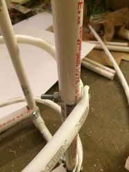
Closer shot of PVC screws

Another shot of the screws


So with that, I decided to get started on figuring out how to get the actual walls around the frame. For this, I went out and bought 8 pieces of large poster paper. This paper shouldn't be glossy on either side and should only cost like $0.79 per sheet (Which was what I bought them for each).
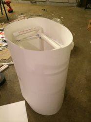
Test paper wrapped around frame to give idea of size
View of inside


Since the circumference is a bit too large for a single piece of the poster paper, I got two sheets and lightly taped them together to try and get an estimate on total length required as well as the overlapping portions. This was used in the next step where I basically did the gigantic poster paper version of the paper layering I did on Day 1.
Gluing together poster sized paper to make large "layered" paper.
Shot of long layered paper. Long as in about 5 feet long.


That all said and done... well, I kinda stopped there cuz I just need to wait for the paper to dry overnight at this point.
Day 9
Date: 6/4/15
Time spent: ~5 hours
Show/Hide Day 9
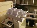
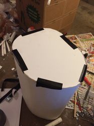
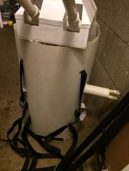
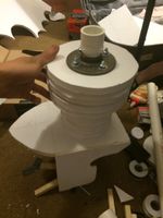
Smokestack Backpack


Yikes. Five day hiatus because I was lazy. So basically what I worked on today was getting this smokestack finally worked out and getting it closer to final. Keep in mind that I decided to try and make this a legit backpack with a hollow inside that I can carry shit in.
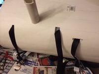
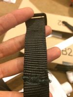
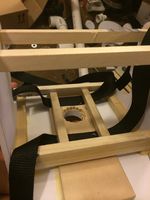
That said, the primary things I worked on was finalizing the location of where the shoulder cannons would be mounted in relation to the PVC frame for the backpack and whatnot. Overall, I'm quite happy about the size and proportions of everything in relation to my body. I believe at this point, while I don't think I took a photo, the shoulder cannon's mount has been bolted into the PVC frame by this point. With proportions and size all in place, all I had to do now was get the straps bolted into place so the whole thing would be held in place without me holding it lol.
For this, I decided to go with two diagonal cross straps that made an X along my chest and a third strap that went around my torso to balance the whole thing so it wouldn't lean to one side due to the weight of the shoulder cannon. And because I'm too lazy to explain the rest, have a gallery.

"Backpack straps" to keep the whole contraption connected to me
Angle of the whole thing lashed together to my body

Another shot of the frames

Overview shot.

Straps bolted in
Picture of the wall panels for the smokestack backpack. Hole will be cut out to bring the shoulder cannon's over
Holes for the straps cut out


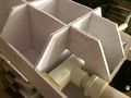
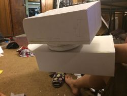
With the straps and wall panel mounted, all I had to do was cover the bottom with an actual layer of thick foamboard. Unfortunately, due to some minor miscalculations with the side panels, one corner of the PVC frame actually stuck out too much so that the foamboard couldn't fit snugly in.

The simple solution to that was just to carve out the foam board, kek
Carving out the thick foamboard to account for the PVC's positioning
Gorilla glue drying with the bottom of the whole thing drying


And then the final shots.
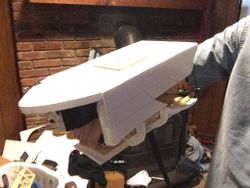
Backpack drying with detached shoulder cannon
Top view of backpack with PVC frame

Further shot of the whole thing


Other Stuff

Day 10
Date: 6/4/16 through 6/10/16
Time spent: ~8 hours
Show/Hide Day 10
Umf. What an update. I didn't feel like I'd worked on enough stuff to make an entire blog post for the past 5 days so I just kind of didn't... and now I suddenly have a lot going on. A lot of the waiting time was just from waiting for parts to ship to me or having a chance to buy more materials lol. Lots of electronics and various small tidbits like grommets, dowels and more screws. Never enough screws. Remember this.
Legging Armor

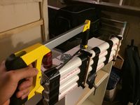
So I actually didn't make a ton of progress here, but I've figured out the general idea on how to do Furutaka's leg armor shit on her shin and thighs. Basically I'll be crafting "foam armor" with craft foam, styrene coating and some wood plates to hold the torpedo launcher and catapult in-place. So to start, I had to first make some craft foam strips that would act as... well, my armor. I cut these into strips that were approximately appropriate to my leg proportions and got to gluing them together since I could only find 8.5" x 11" sheets at my local craft store.

Gorilla gluing craft foam together with clamps
Clamped craft foam
Gluing the craft foam together
Longer pieces of craft foam being clamped


So now I had to wait for these to dry... and not be lazy because I really didn't want to work on this part. Anyway, aside from that we also have the components that go onto these.
Torpedo casing

Not exactly a whole lot going on here. I just cut out the casing base and top. I need to get the leg armor part working before I can figure out where and how to attach the connector piece to this whole thing so this part's on hiatus for now.
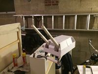
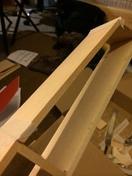
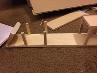
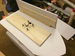
Seaplane Catapult
So this part was actually a bit fun, though tedious. This one was simple woodcraft and cutting dowels to the right size, shape and sanding them properly. I'll just attach a gallery here since it should be pretty self-explanatory.

Leg mounted seaplane launcher progress
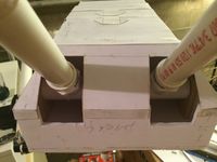
Prototyping angled portion of seaplane catapult
Dowels being put up with wood glue. Make sure to have tacky glue.

Dowels being put up with wood glue. Make sure to have tacky glue.

Glue and supports applied

Different angle of mostly finished seaplane catapult.

Diagonal supports inserted on Furutaka's seaplane catapult
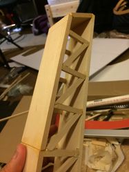
Closer shot of the front edge of the seaplane catapult
Final product minus paint and minor additions


Smokestack Backpack Top


So this one was interesting to think through, but I didn't actually manage to make too much progress. Basically, imagine a pot and a lid. Now imagine my smokestack thing being the pot and now I'm trying to make the lid. This component shouldn't be too complex, but I first needed to start with a sheet that would wrap around the current smokestack backpack so it'd fit snugly. This was accomplished simply by cutting some poster paper into 5 inch strips and layering them 4 times like I did with the backpack's wall lining. The rest I've managed to do was get the paint going and... well, that's about it. I let it sit for 24 hours but it hadn't quite dried so I let it sit again last night so I'll probably to work on that tonight.
Shoulder Cannon and Mechanized Turrets


This is where the majority of my time went with this one. Basically, I had to figure out the dimensions of the whole arm cannon base and turrets so that they made sense, weren't too bulky, had good proportions and could support the motors and wiring. This started out, like all things, with some diagrams. The thought and time that went into this portion was actually much larger than the other parts because I couldn't decide on the exact dimensions for the longest time since I was trying to figure out the optimal dimensions for both ease of making, managing and aesthetics. Eventually, I decided on the dimensions drawn on the board... or so I thought. More on this in a bit.
As soon as I was done with the planning for that portion, I went over to trying and attach a servo motor to the cross-section of a PVC. So this part was ridiculously annoying because as you might know, a PVC is kind of hollow and the cross-sectional component of a PVC is... well, let's just say there isn't a whole lot you can attach things onto. After pondering this for a few days, I finally decided to get some aluminum heavy-grade servo horns that could also take proper 3/32" screws, which were both small enough to drill into dowels but strong enough to withstand any kind of force the servo would apply. I decided that I would then screw through the servo horn and drill into a small 5/16" thick dowel which would be fit through the horizontal of the PVC via two holes I would drill in. This probably doesn't make much sense with just words so here's a quick gallery of the end-product.
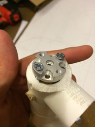
Different angled shot of servo horn on PVC
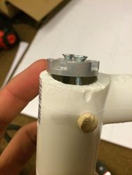
Another angle
Shot of how the servo horn attaches to the PVC's cross-section securely.


So with this, it's actually great because the PVC can now be extremely securely fastened to the servo horn. This is a much better upgrade from the janky shit I had a few days ago with square dowels and 1/4" screws lol.
So that's all good and done. Now time to try and figure out how it fits onto the base...

Uh oh... the barrels and servo motor don't fit into the base... Notice how the motor sticks out of the right side of the base. Realizing this, I had to redraw the base to give it an extra inch of leeway on the width to barely fit the motors in. I didn't like this decision since now the turrets are a bit disproportionate to what I had originally wanted, but alas I need to fit the motor in somehow.


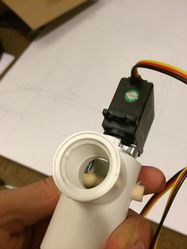
That fixed and all good, the motor and barrels would now fit into the space allotted. Now I had to figure out how to actually mount the damn thing. After thinking for a little bit, I decided the best way to do this was use an intermediary PVC which would slot into the horizontal cross-section of the two barrels and have that held up via foam board slottings.
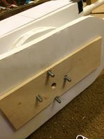
With that done, now it was time to mount the motors. I decided that since the servos already had some screw holes, I would utilize those with a 5/16" x 5/16" square dowel and drill it into there. Doing that with both sides, I simply built a platform from more wood that would act as a flat base and I ended up with something like this.
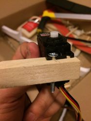
Showing how the servo motor is secured to the cannon
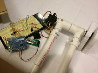
Shot of servo and turrets up and running with arduino
Different angle of electronics

Closeup of the servo motor in mounting position


Oh, and did I mention that I went ahead and did a mock wire-up while I was at it? This turret is technically fully functional in terms of y-level elevation :)
So overall, the past few days, while frustrating at times, was very productive. I'm actually picking up momentum once again so we'll see where I get tomorrow.
Also bonus image of something my friend and I wrote cuz kek

Day 11
Date: 6/10/15 through 6/16/15
Time spent: ~15-20 hours idr
These "Days" are actually getting dumb because I'm posting like per-week progress at this point lol.
Show/Hide Day 11
I think I've been getting lazy with the posts. This is basically a week of progress in one post.
Cannon Mechanization


So this one will be interesting. I went through like three phases over the past week for this so I'll write about it as if I'm going through it.
To be quite honest, the task of actually creating the mechanized turrets was (and still is) a bit of a daunting task. It's been forever since I've worked with circuits and kinematics and I've never had to worry about the finer numbers with cosplay before. That said, the best way to get used to something is generally just diving in head first so... well, I started with what I could figure out and got started.
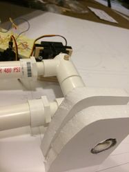
The first thing I did was done on day 9. This was actually attaching the servo motor to the PVC's cross-section. With that done, I had to figure out how to mount and house the motor and moving components in the turret's casing itself. This was relatively simple as all I did was get a thinner PVC that slid into the existing turret barrels and could move freely. This is shown in the images to the right.
With that done, I had to actually construct the casing for the cannons to house the components into.
Diagram of turret side walls
Cutout

Cover of arm cannon
Bottom of arm cannon's turret with barrel pieces mounted into place.


That done, I decided to work on the control grip which would house the buttons which would be connected to the circuit board. This would be accomplished quite elegantly by sliding a smaller PVC pipe into a larger one that fit snugly and cutting each pipe in a specific manner as shown to the right.
This ended up working really well because of the heights of the buttons and the thickness of the PVC walls. It ended up being a snug fit and they're quite comfortable.
The control grip with the buttons will be enclosed in this.

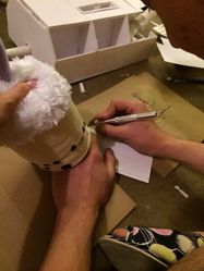
Holes screwed into smaller PVC and buttons bolted in
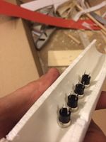
Underside
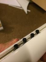
Larger PVC piece slid on top
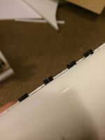
Buttons barely poke out, making for a comfortable press


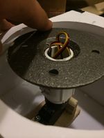
This done, I still had the motor which would rotate the cannon left and right to mount. This would be simply mounted to the roof of the cannon's casing and attached once again to the cross-section of a PVC.
With all these parts now ready, I wired them up to the circuit board and tried it out.
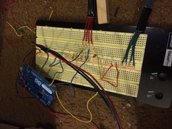
Breadboard with turret wiring

Control grip wired

Shot of multiple components


Now wired up, I decided to give it a spin and powered up the arduino and whatnot. After some difficulties, I realized that the thing was nigh impossible to actually use because of the way the center pipe was mounted on the servo motor and it was causing too much sheer force and bending it. This was with the PVC naively attached to the servo as-is and expecting to move the entire turret by simply "holding" the pipe in-place.
Going back to the drawing board and trying to resolve the issue, I figured that the primary issue here was that there was
- Too much sheer force along the pipe and it was difficult for the motor to overcome it.
- Too unstable and wobbly
- Too much pressure on the bottom of the turret and the board that acted as the base (The friction between the rotating portion and the stationary portion)
- This part was caused because I was originally holding the PVC pipe in-place by adding a horizontal dowel through the PVC and keeping it stationary via... well, applying pressure upwards.
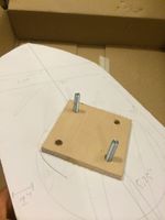
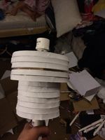
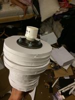
To overcome this, I decided to stop using the horizontal dowel and instead use this handy thing.

Meet the might floor flange. It's made of metal and it's heavy! Though honestly, this was a good investment I believe because holy shit this is sturdy as hell. I'll just add a gallery for now for the various layers and processes I did with this.
Base of cannon being reinforced with basswood.

Other side
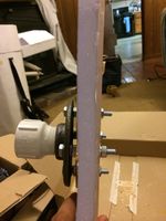
Example of how floor flange will connect

Different shot
Attached to the motor

Support pieces sliding in

Arm cannon base sliding on
Some leeway left for nuts and washers


That done, I thought I was basically set and could go ahead and power the whole thing and go WHREEEEEEEE and have fun. Unfortunately, the motors were still very weak and the turrets moved slowly. After trying to figure out the issue for a good two hours of fiddling with the circuit and googling, I finally figured out that I'm a complete dumbass and that I came very close to frying my entire Arduino and $50 worth of motors. Turns out my power supplies and various numbers were completely off and I had to completely redo everything and buy another $50 of electronics between batteries, adapters and components. Whee.

So yeah, we'll see where this goes when my stuff comes in this week.
Shin/Leg Armor
So yeah, this is the thing the leg torpedoes are stuck to. I hate this part the most. Fuck.
So I've linked this page before, but I suggest just looking at the "Construction" page for this website FIRST, THEN looking at my images cuz it's probably easier to read that then me explain it.
Different angle
Craft foam being glued into shape of shin guard
Different angle

Shin armor frame made of craft foam
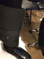
Shin armor
Laying out styrene coating and taking measurements

Styrene layer hot-glued on
Hot gluing further pieces of craft foam to other sections of shin
Top piece with styrene coating applied
Different angle


Torpedo Rack
This is fun stuff. As in not fun stuff. I'm starting to get incredibly lazy. Have a gallery.
Torpedo rack holes
other side
Torpedo rack base
Torpedo rack under construction

Everything but side panels applied
Shot of torpedo rack from top

From back

Underside
Example of torpedo rack mounted on leg. Not stabilized or tightly secured
Spacing between shin armor pieces to fit torpedo rack. Need to make this gap smaller.


Arm Cannon Frame


'Day 12 New!
Date: 6/16/15 through 6/26/15
Time spent: ~25-30 hours. Hell if I know
Whooo 10 day hiatus from posting.
Show/Hide Day 12
I think I've been getting lazy with the posts. No denying it now.
Back Half of Arm Cannon


So if you look at Furutaka's arm cannon, you'll notice that the back cannon is actually elevated a bit up so... you know, the cannons don't shoot into each other. That said, I decided to just make the elevating platform consist of many half inch thick discs. To allow for attaching the actual turret, I once again used a steel floor flange. To keep that stable on the foamboard (Which isn't the most rigid material ever), I simply threw in a layer of wood.
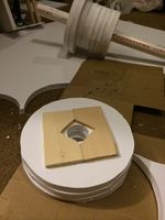
Turret elevation rings being assembled
Turret elevator
Different angle


That done, I decided to work a bit more on the back piece for the arm cannon, the part that the elevator would stick into. This by itself was actually pretty simple since the only thing I really did was add in straps to attach it to my arm. Quite simple, really. I used a tri-glide strap holder in a way it's definitely not meant to to keep it in place. As a note, I did sew the straps together after sliding it into the tri-glide.

Arm cannon's back half

Back component of arm cannon with turret elevator
Top side
Arm band with tri-glide... these aren't meant to stop belts loll;
Gluing the straps onto the cannon


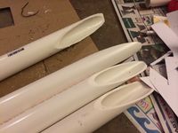
Torpedoes and Holder

This part was pretty fun. My 3D printed torpedo propellors came in so I just slapped them into the PVC tubing and painted those babies up. Ended up looking pretty slick! Aside from that, I also added on the connection point of the torpedo casing to my leg.
Torpedo propellors!

Different angle

Gluing them together
Rest of the turret barrels
Torpedoes with gesso being applied
Torpedoes getting first layer of paint
Taping the torpedo to apply black paint layer
Another shot
Applying black paint over masking tape
Torpedoes finished!
Torpedo casing!
Other side!


Front Half of Arm Cannon

So this is just going to be mostly galleries since it should be pretty self-explanatory. For this first part, it'll be the preliminary construction of the walls for the front half and getting the PVC grip in-place. Something that I kept high in my priority was to make many components of this removable so I had easy access in case something broke. The last thing I want is the wiring in the grip to fuck up and suddenly I can't get to it because I glued everything together :(
Working on building side walls of front half of arm cannon
PVC grip in-place
Holding up in-progress cannon
Upside-down, but should look something lik ethis.
Buttons! These will control the turrets

Holding the cannon
Another shot of the front


Then the next part is constructing the bottom half of the front cannon. This is basically creating a hull-like thing that'll attach to the bottom. This will be removable. I also worked on getting a sideways V-cut on the back of the hull as this is portrayed in the actual character design as well. This was a bit annoying to figure out because of the non-angular portions of the hull and whatnot. In the end I just decided to create a wood skeleton inside the foamboard outline I already had. You know, usually you construct the softer part around the skeleton, not the other way around lol.
Working on building the bottom half of the hull's frame
Measurements!
Frame coming to life!
Starting to look like something
Penciled lines indicate where cut will go
Enforcing the bottom hull's frame
Different angle
Closer shot

Bottom hull's curves glued in


The third part is Further working on the top half (I'm doing this in the order I worked on the parts as opposed to realigning them) I cut out parts of the walls as the original image portrays a sideways V-like cut on the side. Aside from that, I also stuck the battery in which will be powering the motors.
Front half of arm cannon with turret on top
Front shot

Angled shot
In-progress shot of both front and back halves of arm cannon


Finally, I worked on both halves to add a platform that would allow me to place some velcro in to attach the two halves together. This was relatively straight forward. By the end of this, the bottom hull looked pretty crazy.
Shot of the platform to put velcro on
A shot of the platform on the bottom hull where the velcro will go on
Two platforms will align
Like so
Two halves velcro'd together
Velcro in shot


Clothes
So I was originally hoping to not have to work on this, but it ended up with me not being able to get away lol. Basically I was hoping I could buy the right kinds of clothes for the outfit but apparently the top portion of Furutaka's clothes, the kinda sailor uniform, is not really a thing. That said, I ended up being a long sleeved one that mostly looked right and went ahead and modified it.
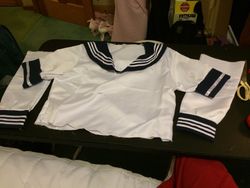
Modified long-sleeve sailor suit. Shortened sleeves and needs center to be cut
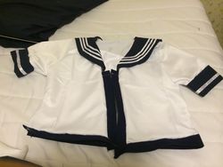
Front cut with cuff things

Semi-final product


And here's me wearing these and the bodysuit
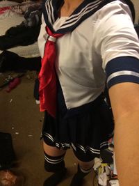
Wearing most of the clothes :)
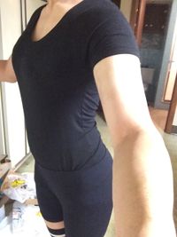
Bodysuit underneath kek


Random other Shit
Battery came in!

Batteries! The acid lead battery is used for powering small vehicles lol;;

Battery charging


And painting the backpack thing!

Top shot of the exhaust pipe
Smokestack backpack and shoulder cannon


And the torpedo rack on my shin armor!

Notes
Do keep in mind that everything I do here is simply a blog and the information and any tips provided are done so as-is. Don't blame me if you try doing anything I do and you blow up your house or anything. Though if you do somehow manage to blow your house up trying to reproduce my steps, do tell me because I'd be really curious as to how someone could fuck up that badly lol.
Cosplay props are fun.
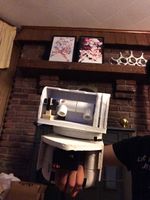
End Result
Lol it's like 3 months after I finished this but I realized I never uploaded pics on here. Here they are.


